Decode 433 MHz signals w/ Raspberry Pi & 433 MHz Receiver
This post will show you how to read 433 MHz codes using a Raspberry Pi. This tutorial was made to complement the Voice Controlling project which needed 433 MHz Unit Code Values to control the wireless switches. If you want to know how to read 433 MHz codes using an Arduino, go to this post!
I learned how to do this by reading this post. So credit goes to Paul Pinault for making this project a reality.
Hardware Requirements
- Raspberry Pi(I used a Raspberry Pi Rev.2)
- 433 MHz receiver(Any type of 433 Mhz receiver should work, but for this tutorial I used a 4 pin variant)
- A breadboard
- Some jumper wires
- A 433 MHz transmitter(I used a 4 channel 433 MHz transmitter Remote)
Installing WiringPi
WiringPi is needed to control the pins on the Raspberry Pi. Which will be connected to the 433 MHz Receiver.
To install WiringPi, SSH into your Raspberry Pi or open up a console, then run these commands:
cd ~/
git clone git://git.drogon.net/wiringPi
cd wiringPi
./build
After running the last command, WiringPi should be installed!
Installing 433Utils
433Utils is made by GitHub user wolfeidau. He gathered a bunch of code and wrote some himself, all about 433 MHz Radio Transmissions, then made a repo of it.
To install 433Utils, run these commands:
cd ~/
git clone –recursive git://github.com/ninjablocks/433Utils.git
cd 433Utils/RPi_utils
make
Now 433Utils should be installed!
Connecting the 433 MHz receiver
As you can see in the picture, my 433 MHz receiver actually has two Data-pins. Why it has two pins I don’t exactly know, but a possibility is it is used to easily connect two output-sources, or two different Arduinos. In this project however we will only need to use one of the pins. I used the one closest to the GND-pin. If anybody knows why it has two Data-pins, let me know in the comments!
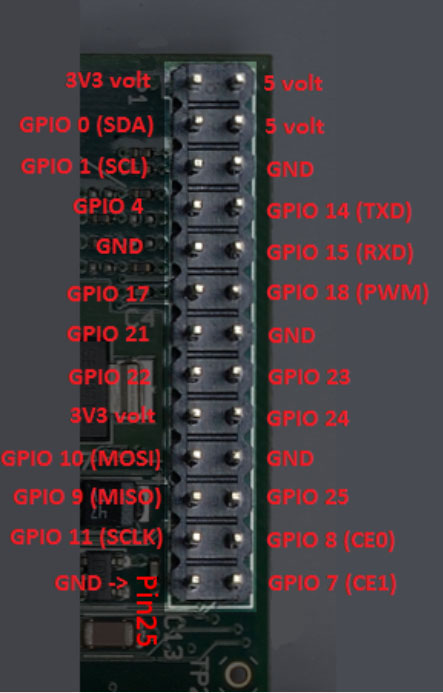
The code we will be running will be speaking out to the GPIO2 pin, according to this site, GPIO2 is GPIO pin 21 on Rev.1, or GPIO pin 27 on Rev.2
Here is an image of the P1 pin header on the Raspberry Pi Rev.1. GPIO pin 21 and 27 should be on the same pin on both versions.
Basically the connection between the receiver and Raspberry Pi can be described with a table.
[table width=”200″ align=”center”]Raspberry Pi Pin, 433 MHz Receiver Pins
GND,GND
5V, VCC
GPIO 21/27,Data
[/table]
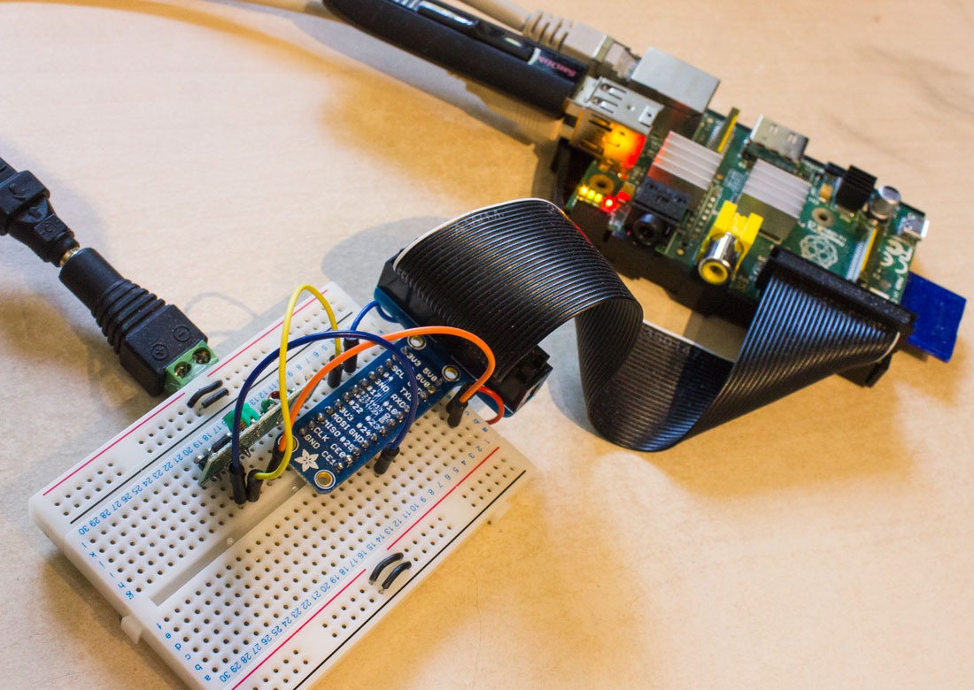
Here is how the connection looks like to me, I’m using a breakout board and a breadboard.
Running the code
To start listening for the 433 MHz codes, start the RFSniffer program we got from 433Utils, using this command.
~/433Utils/RPi_utils/RFSniffer
I used a simple 4 channel 433 MHz Remote to send some 433 MHz codes to my receiver.
Now bring your 433 MHz transmitter remote VERY close to your receiver, and press some buttons. The range of the receiver is not very far on the Raspberry Pi, so make sure you bring the remote as close as you can.
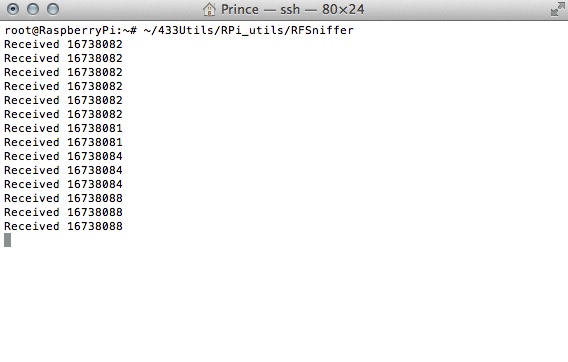
The received codes should print out as you press the buttons on the remote. I’m using terminal and for me it looks like this:
Pressing the buttons on my transmitter prints out values ranging between 16738081- 16738088.
Congrats, you now know how to print out 433 MHz codes using your Raspberry Pi & 433 MHz Receiver!
If you have any questions feel free to ask me by using the Contact page or by commenting below.


